A personal engineering project
Work in progress · Hardware bring-up

Building an Autonomous Mecanum AGV

A personal robotics project for an indoor platform designed for omnidirectional motion. I designed the custom mechanical parts, integrated the electronics, and developed the standalone C motor-test firmware. Perception and navigation are planned.

From workbench to autonomous platform
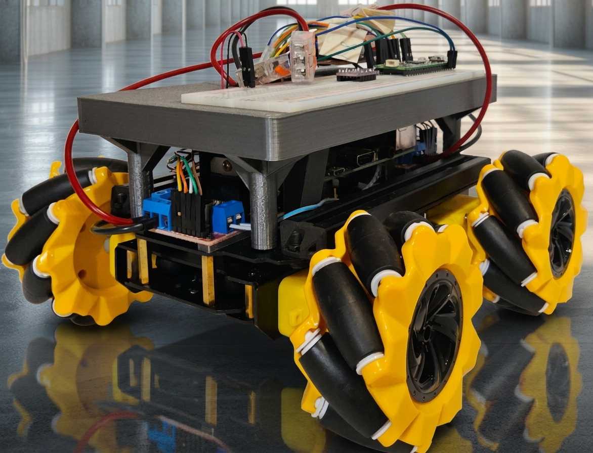
FIG. 01 / THE CURRENT PROTOTYPE
Angled workbench view of the real Mecanum AGV, with yellow wheels, a custom grey first deck, breadboard, and exposed prototype wiring.
Current prototype · First custom deck installed · Motor tests completed
Across the stack
  • C
  • C++
  • Python
  • Raspberry Pi
  • RP2040
  • ROS 2, integration planned
C motor tests verified · C++ / Python / ROS 2 planned

Not just forward. In any direction.

The goal is a compact indoor platform that can position a future camera or small gripper—without turning the entire robot first.

Mecanum wheels make lateral movement possible. I’m building the mechanical and control foundations to turn that capability into useful, predictable motion.

Intended motion capabilities

TOP VIEW

Reposition sideways without turning.

Illustrations of intended motion capabilities. Camera and gripper are future payloads, not installed equipment.

An off-the-shelf base. Custom integration.

I started with a purchased drive base, then designed the parts that turn it into a layered platform for electronics and future sensors.

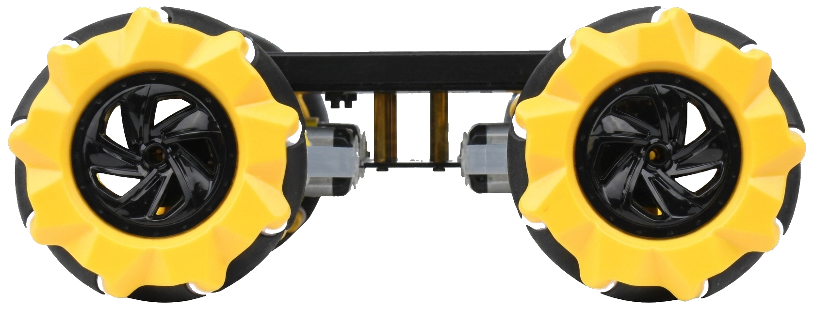
  1. 01 / Purchased base

    Purchased Mecanum wheelbase with yellow wheels, DC motors, and the metal chassis before the custom deck is added.

    Purchased

    Purchased chassis, Mecanum wheels, and DC motors form the drive base.

    Purchased

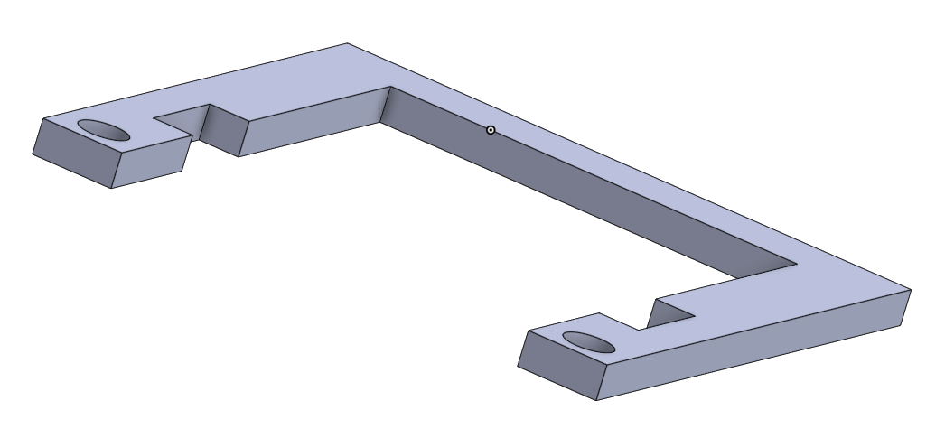
  2. 02 / Motor-driver mounts

    CAD render of the custom motor-driver mount, showing the open frame and mounting holes that hold the board clear of the chassis.

    Designed · Printed · Installed

    My printed mounts keep underside board contacts clear of the metal chassis when the motor drivers are fastened down.

    Designed

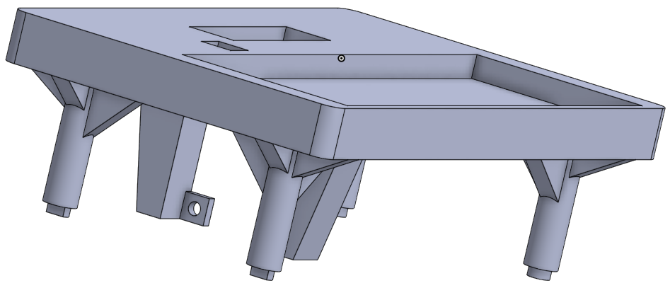
  3. 03 / First custom deck

    CAD render of the first custom deck, showing the rectangular upper platform, mounting legs, and reinforcing ribs.

    Designed · Printed · Installed

    My custom 3D-printed assembly adds a stable upper mounting surface and separates the electronics into layers.

    Designed

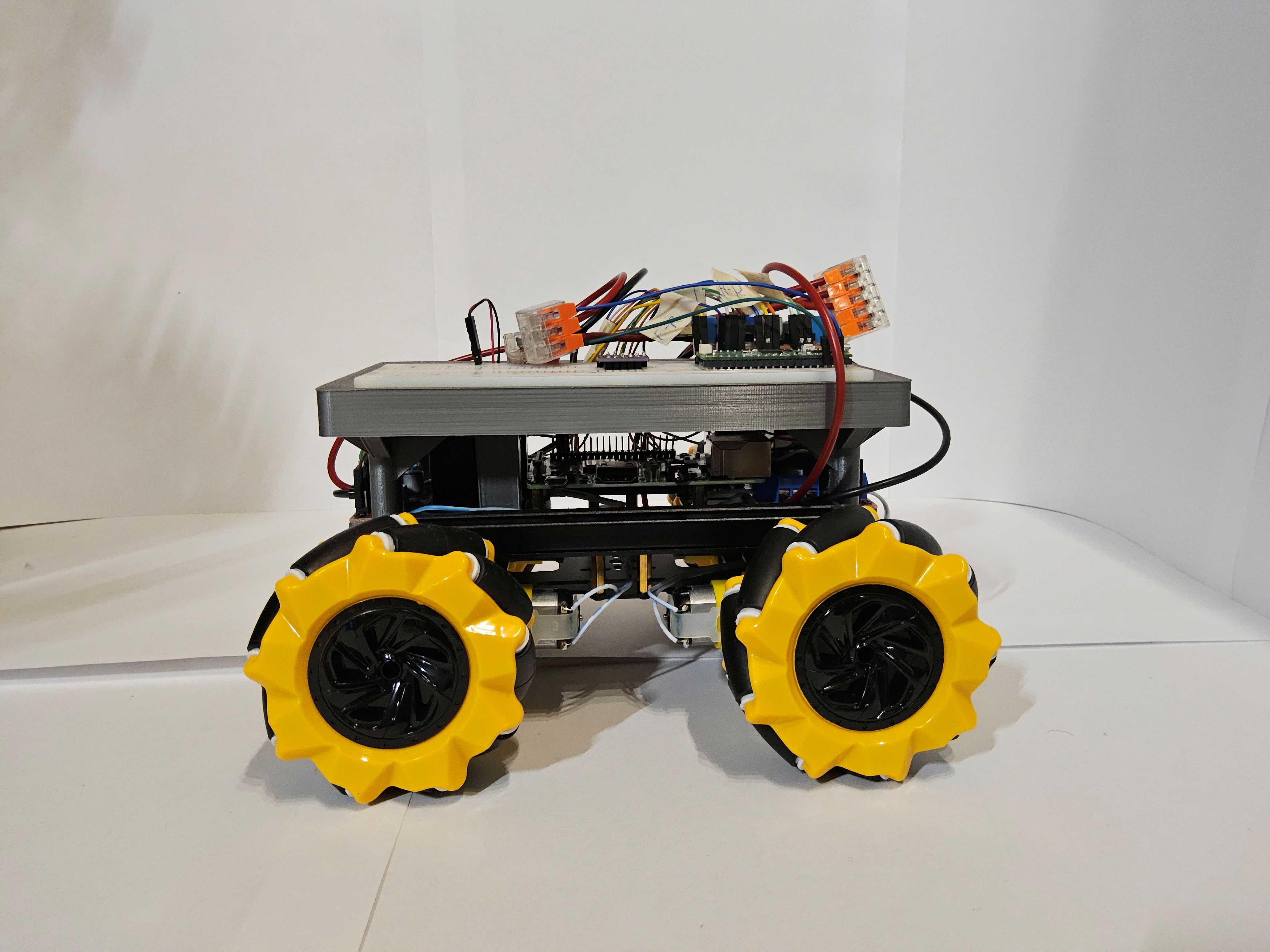
  4. 04 / Assembled prototype

    Side view of the Mecanum AGV showing the custom grey first deck and supports above the chassis, electronics between the layers, and yellow wheels.

    Assembled · Hardware bring-up

    The platform houses the Pi/Pico compute layers, power distribution, and mounted IMU. A second deck is designed for future LiDAR integration.

    Integrated

STL models and PDF drawings for the first deck and motor-driver mount are available on GitHub.

STL models & PDF drawingsPurchased chassis · Elektronica voor jou

Two layers of hardware. One evolving platform.

The custom deck gives each part a place. Below it sit the main computer and motor drivers; above it, the embedded controller and a sensor awaiting bring-up.

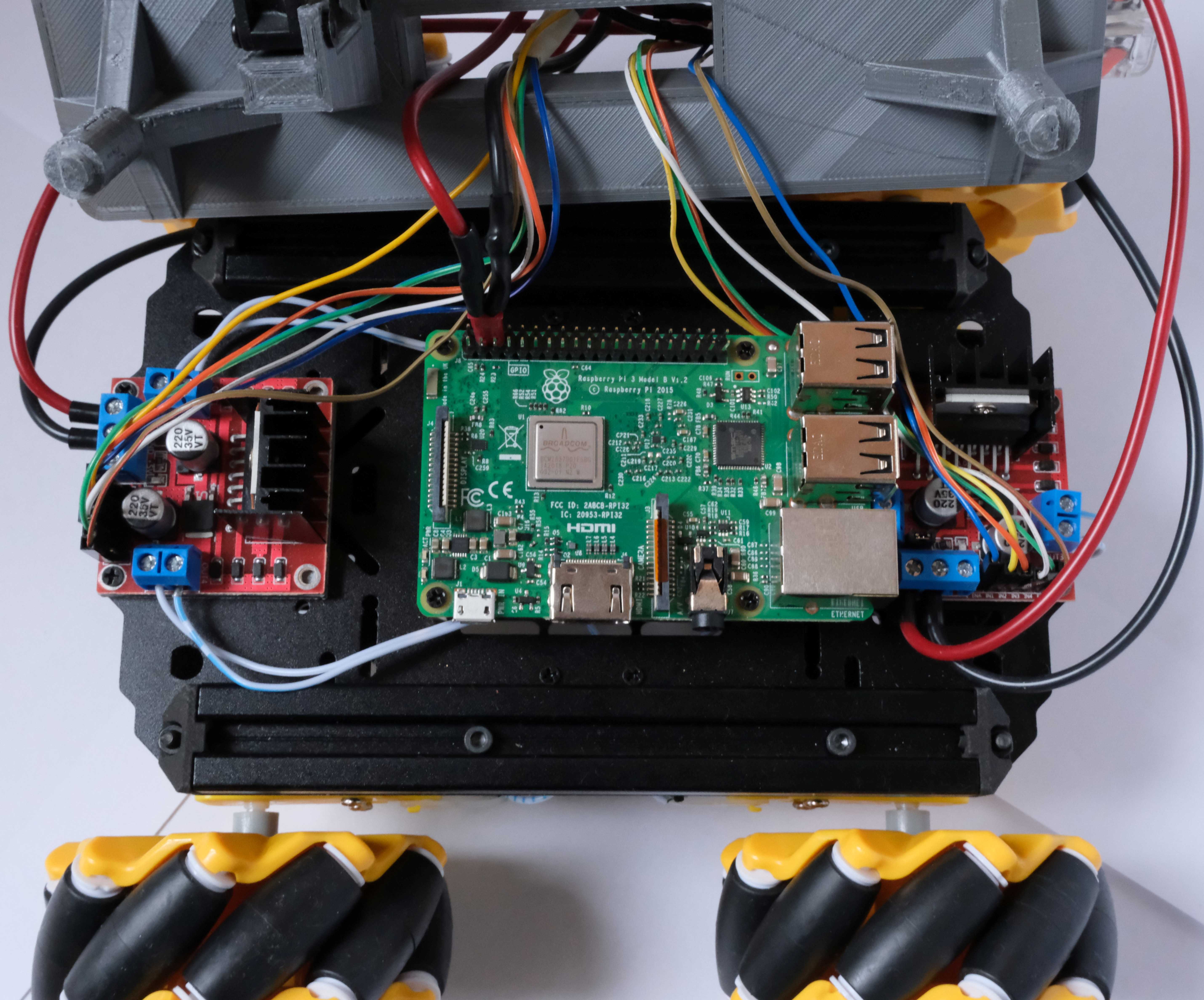
Lower deck / Computing & motor drivers
Lower electronics layer with the Raspberry Pi 3 B between two red L298N motor drivers, underneath the custom deck and surrounded by prototype wiring.
Lower layer · Raspberry Pi 3 B and two L298N motor drivers

Computing, power & cooling

Raspberry Pi 3 BSetup verified
The main computer for the future perception and navigation stack. Headless Ubuntu and Wi-Fi SSH access are working.
Two L298N motor driversWired · Initial motor tests
The drivers translate control signals into motor drive for the four wheels. Initial motor tests have been completed.
Integrated cooling fanInstalled · Wired
Installed and wired directly in front of the Pi 3. The custom deck provides the mounting point, supporting airflow around the computer.
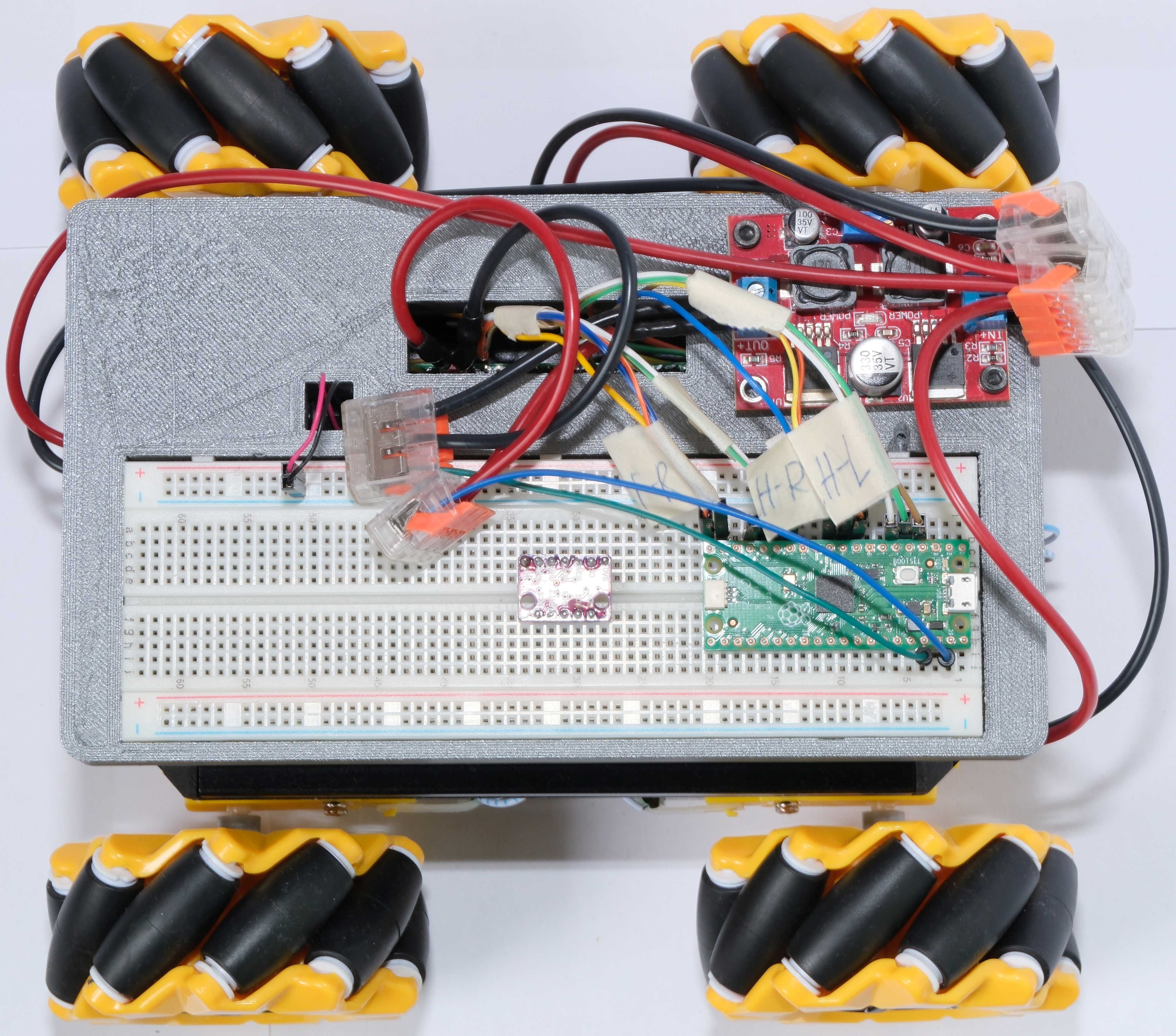
Upper deck / Embedded control & sensing
Top-down view of the AGV showing the Raspberry Pi Pico and purple BMI160 IMU on the breadboard, open power wiring, and four yellow Mecanum wheels.
Upper deck · Embedded electronics in their current prototyping state

Motor control and sensing, within reach.

The Pico and mounted IMU sit on the upper breadboard. This accessible layer is where motor-control wiring and the IMU sensor interface come together.

Raspberry Pi PicoC motor-test firmware verified
Runs the standalone C motor-test firmware. The Pico-to-L298N pin assignments have been validated on the robot; feedback control and IMU acquisition remain planned.
BMI160 inertial sensorMounted · Bring-up pending
Mounted for future platform-motion measurements. Sensor communication, data acquisition, and calibration are still pending.

Wiring diagrams & hardware files

Validated motor-driver pin assignments, the Pico-to-L298N wiring illustration, and the power-distribution diagram are available in the public project repository.

See how the system fits together
Wiring & pin assignments

Two compute layers. Clear responsibilities.

The Pi is intended to handle perception and navigation; the Pico handles direct motor actuation and will acquire IMU measurements.

System overview

  • Verified setup / test path
  • Next integration
  • Planned

Development laptop

Remote development

Connected
Wi-Fi / SSH · Verified

LD19 LiDAR

Environmental perception

Not integrated
Sensor integration · Planned

High-level computer

Raspberry Pi 3 B

OS ready

Headless Ubuntu Server 22.04 · Wi-Fi SSH verified

Intended high-level stack · Planned

  • Python / ROS 2 Humble
  • State estimation
  • SLAM
  • PRM global planning
  • Local planner

UART preferred · Link pending

BMI160 IMU

Acceleration & angular rate

Mounted
SPI · Bring-up pending

RP2040 · Embedded actuation

Raspberry Pi Pico

C motor test verified

Standalone C motor-test firmware · Built and tested on the robot

Firmware & integration · Planned / in development

  • C/C++ control firmware
  • IMU acquisition
  • Mecanum kinematics
  • Low-level control
Pico → L298N
4 PWM + 8 direction GPIO · Motor-test path

2 × L298N

Dual-channel motor drivers

Wired
Four motor channels · Initial tests completed

4 × DC motors

Mecanum wheels · No encoders

Motor tests completed

Node labels describe hardware/setup status. Lines describe connection status. Integrated autonomy and sensor fusion are not yet demonstrated.

A closer look at the decisions

The motors turn. Finding a usable baseline.

Standalone C firmware brought all four motor channels into operation. The initial tests and a short PWM-frequency experiment now form the retained baseline for developing feedback control.

Initial motor testRecorded test
Initial motor-driver tests showing unequal responses to equal duty commands. The subsequent PWM-frequency findings are documented on GitHub.

Observations & findings

Finding a usable PWM baseline.

Observation.
The same duty command produced unequal motor responses; two motors initially remained stationary.
Experiment.
I varied PWM frequency, considering motion steadiness, differences between motors, audible humming, and supply-power consumption.
Result.
At approximately 1.5–2 kHz, equal duty commands produced visibly more similar responses and straight travel on the tested level surface. Audible humming remained.
Motor-test baseline retained

Qualitative findings under the tested conditions. Wheel speeds, current ripple, and driver losses have not been quantified.

Motor-test findings & source
Why does PWM frequency matter?

Higher PWM frequencies can reduce motor-current ripple and shift PWM-related tones beyond the audible range. They also involve more switching events and associated losses. Lower frequencies leave longer intervals for the driver’s switching transitions and can reduce switching losses, with more current ripple and audible humming as possible trade-offs. The retained setting is a practical operating choice for this prototype.

Next integration

Feedback control with the IMU.

Planned

Motor bring-up is complete for this stage. I’m retaining the tested configuration and moving on to BMI160 acquisition, Mecanum kinematics, and feedback control. Extensive per-motor calibration is deferred unless later tests justify it.

There are no wheel encoders. The IMU measures platform acceleration and angular velocity, so motion estimates accumulate drift. Short maneuvers, checked against floor markings or video, will provide an initial way to evaluate the controller.

Built in stages. Documented as it develops.

A working prototype is built through small, verifiable steps. Here is what is in place—and what is still ahead.

STAGE 01

Completed

The foundation is in place

  • Custom first deck and driver mounts
  • Initial electronics wiring
  • Initial motor tests
  • Standalone C motor-test firmware on GitHub
  • PWM-frequency experiment and straight-line trial
  • Published STL models, PDF drawings, and wiring
  • Headless Ubuntu Server 22.04 on Pi
  • Laptop-to-Pi Wi-Fi / SSH access
STAGE 02

Next

Understand the motion

  • Pico-to-IMU SPI bring-up
  • IMU acquisition and calibration
  • Mecanum kinematics and control
  • Evaluate IMU-based feedback in short motion tests
STAGE 03

Planned

Build toward autonomy

  • Pi-to-Pico link and protocol
  • Second deck and LiDAR integration
  • ROS 2 and state estimation
  • SLAM, PRM, and local navigation
  • Future camera or gripper payload

The public repository contains the hardware-tested C motor example, build instructions, observations, and hardware exports. Closed-loop control, sensor fusion, and integrated autonomous navigation remain planned work.